OSI ( Open Systems Interconnection ) model was developed by ISO ( International Organization for Standardization – Technical Committee 97 ) in 1978. This model was fixed a little bit and published as “OSI Reference Model” in 1984. OSI model, which is accepted by all world very quickly, basicly defines how network devices communicate together. Before OSI model , every vendor was using its own specific computer network. They were defining all the rules according to their product’s working principles. For example IBM was using their own devices only and no more brands other than IBM was working on this network.
But after years , many vendors started to develop their own devices too. And it was a big requirement that providing communication between different vendors. OSI ( Open Systems Interconnection ) model defined protocols which is not specific to vendors and provided communication between different vendors which use their model. This model doesn’t change according to a hardware, computer network type or software. It became an industry standard very quickly. OSI ( Open Systems Interconnection ) model consist of 7 layers which define network communication. These layers are ;
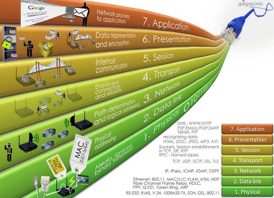
- Physical Layer
- Data Link Layer
- Network Layer
- Transport Layer
- Session Layer
- Presentation Layer
- Application Layer
As you can see from the figure above, Application Layer ( Layer – 7 ) is the highest level of the model while Physical Layer ( Layer – 1 ) is the lowest. First three layers are defined as “Media Layers” and Layer 4-5-6-7 are defined as “Host Layers”. Information is began to sent as “Data” at Layer – 7 and divided to “segments” at Layer – 4 ( Transport Layer ). This segmentation provides the receiver device can get the information with the right sequence. Address values are added to “segments” at Layer – 3 and our information’s name is a “packet” anymore. MAC addresses are added to “packets” at Layer – 2 and “frame” structure occurs. Finally, “frames” are converted to bit series at Layer – 1 and it is ready for transportation anymore.
Layer – 1 : Physical Layer
Physical Layer defines the structure that our data in a cable. Datas are transported as “bits”. This layer defines how “1” and “0”s will be converted to radio, electric or light signals. Sender converts the bits to signals, and receiver converts back them to “1” and “0”s again. For example a “hub” is working on Layer – 1 of the OSI Model because it sees the data as an electric signal. Lots of hardwares work in this layer like Cables, RS-232, USB, DSL and etc…
Layer – 2 : Data Link Layer
Data Link Layer defines the rules to reach the Physical Layer.Access methods like ethernet or token ring works on this layer. These access methods processes the data due to their own protocols. Information ( data ) is a “frame” in this layer. Frames provide us sending the data in a sequence. Most of the process which is made at Data Link Layer is processed on network cards.Provides error detection to data which comes from Layer – 1 also. In this Layer technologies like ethernet, HDLC, token ring, L2TP are used.
Layer – 3 : Network Layer
Network Layer is the layer which router information is added if the packet is needed to sent to a different network. In this layer messages are addressed and logical addresses are converted to physical addresses too. Internet Protocol ( IP ) works in Layer – 3 so that ip routing too is made in here. Protocols like IP ( IPv4 and IPv6 ) , ICMP , ARP and IGMP works at Layer – 3.
Layer – 4 : Transport Layer
Information is labeled as “segment” in this layer. Transport Layer provides us the transportation of the information. Protocols like TCP and UDP work at this layer. This layer also provides QoS ( Quality Of Services ) too for the upper layers. Error detection is made for some protocols ( like TCP ) SCTP and DCCP protocols also work at this layer.
Layer – 5 : Session Layer
Session layer provides connection between applications on two different computers. If one computer is in a communication with lots of computers, session layer provides to choose the right computer to communicate also. This is made with dividing the informations with different sessions. NFS, SMB, ISO 8326, ISO 8327, ITU-T T.6299 and Netbios work at this layer.
Layer – 6 : Presentation Layer
Presentation Layer converts the data to the way that receiver computer can understand it. So that different softwares can use the data of each other. This layer defines “how the data is presented”. Format of the data is defined in here too. In addition processes like encryiption, zipping, de-encryiption are made at Layer – 6. In this layer picture formats ( like jpg, png etc. ) , ASCII, EBCDIC work.
Layer – 7 : Application Layer
Application Layer provides an interface between computer application and network. Only application layer doesn’t provide any service to others. This layer provides applications working on network. HTTP, FTP, SMTP, DNS and SNMP protocols work on this layer.
OSI Model provides efficent troubleshooting too. For example if a device is down in the network, troubleshooting begins from Layer – 1 ( like checking the cable of the device. ) After if there is no problem in Layer – 1 , Layer – 2 is checked ( If device’s MAC address appears in the MAC address table or not ) If there is a problem here, Layer – 3 is NOT checked ! If Layer – 2 is OK too , Layer – 3 is checked ( If device’s IP address appears in the routing table of router or not ). This method is used up to Layer – 7 with the same method.